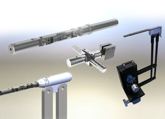
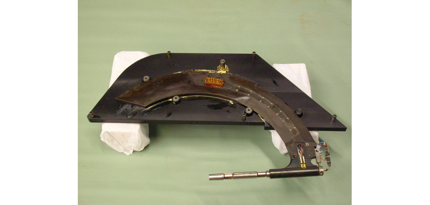
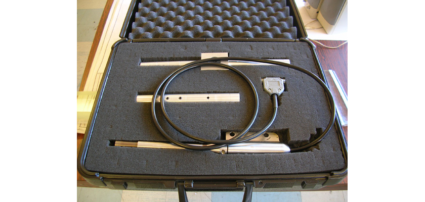
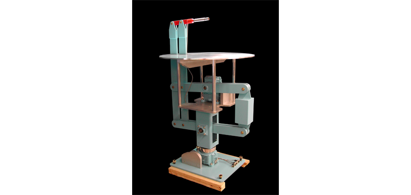
AEROLAB’s new design makes a better Sting Force/Moment Balance.
During the early years of wind tunnel testing, Forces and Moments were literally measured through pan-type “balances.” Although technology has advanced dramatically since those early days, the term “balance” is still applied to the devices used for Force and Moment measurements today.
Balances can be divided into two main groups: internal and external. The group names are derived from their location relative to the test model and wind tunnel test section – internal balances reside inside a test model, while external balances reside outside the test section. Internal Force/Moment balances are almost universally used for measurements in supersonic and transonic tunnels. However, they are also becoming popular in subsonic tunnels.
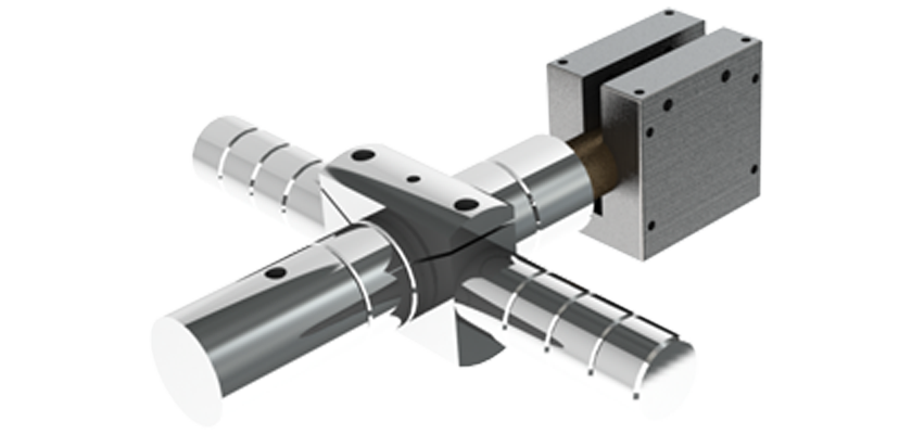
AEROLAB has developed an internal balance cut from a single piece of precipitation-hardened stainless steel – no screws, pins or welds are used. This one-piece design is superior to earlier designs in strength, accuracy and in providing lower interactions between components.
Load Limits
| Sting Diameter & Designation | Normal Force | Side Force | Axial Force | Pitching Moment | Yawing Moment | Rolling Moment |
|---|---|---|---|---|---|---|
| (INCHES) | (LBS) | (LBS) | (LBS) | (IN LBS) | (IN LBS) | (IN LBS) |
| 3/8 L | 1 | 1 | 1 | 12 | 12 | 12 |
| 3/8 EWT | 25 | --- | 10 | 50 | --- | --- |
| 3/8 A | 10 | 10 | 4 | 15 | 15 | 50 |
| 3/8 B | 15 | 10 | 6 | 22 | 15 | 50 |
| 3/8 C | 20 | 15 | 12 | 32 | 22 | 50 |
| 1/2 A | 40 | 30 | 12 | 70 | 60 | 60 |
| 1/2 B | 60 | 36 | 15 | 120 | 70 | 80 |
| 5/8 A | 100 | 75 | 25 | 200 | 150 | 150 |
| 5/8 B | 150 | 100 | 25 | 250 | 180 | 200 |
| 3/4 A | 200 | 100 | 60 | 400 | 200 | 160 |
| 3/4 B | 250 | 144 | 50 | 460 | 255 | 200 |
| 1 | 300 | 150 | 80 | 500 | 250 | 250 |
Performance Specifications
Using modern machining processes such as Wire-EDM (Electrical Discharge Machining), AEROLAB strain gauge sting balances are made from a single piece of precipitation-hardened stainless steel. This one-piece design is superior to earlier designs in strength, accuracy and in providing lower interactions between components because no screws, pins or welds are used.
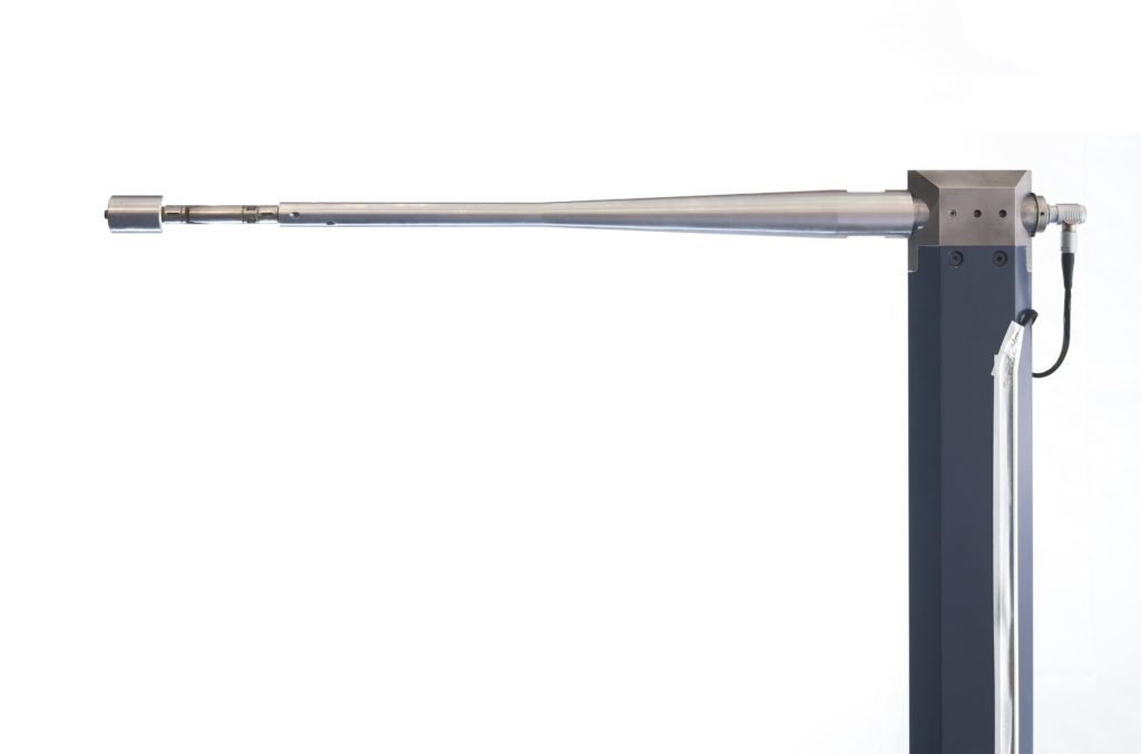
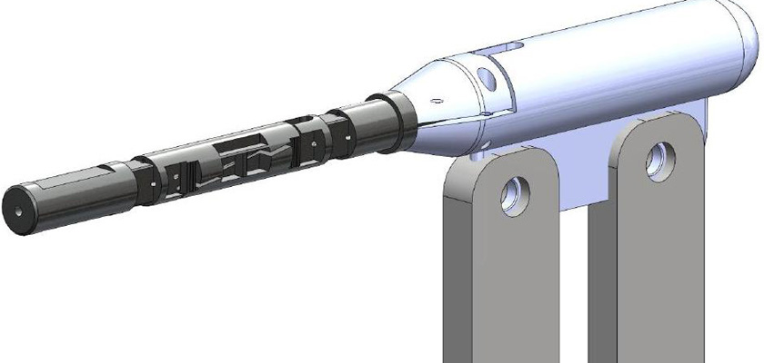
Sting balances are normally designed with cylindrical ends – one end is clamped into the model positioning system, and the other fits into a reamed hole in the model. Test models are secured to the sting with a set screw. To avoid problematic burrs on the sting (burrs can prevent test model removal), recessed flats or grooves are provided. In some cases, balance ends are tapered. Tapered ends provide a convenient mounting method for nose-mounted test models such as missiles.
AEROLAB designed a protective sheath to eliminate two common problems associated with sting balances: the fragile foil strain gauges and fine wires are vulnerable to rough handling, and the sting must be enclosed in the model to protect against airflow over the gauges (which causes erroneous readings).
Optional Features
- Data Acquisition, Display and Control System
- Model Positioning System
- Wind Tunnel Test Models
- High-order calibration matrix
Related Products
Type
- Balances
Performance Specifications
AEROLAB designed a protective sheath to eliminate two common problems associated with sting balances: the fragile foil strain gauges and fine wires are vulnerable to rough handling, and the sting must be enclosed in the model to protect against airflow over the gauges (which causes erroneous readings).
Questionnaire
The following questionnaire is intended to streamline the choice of a new AEROLAB Strain-gage Force/Moment Sting Balance. Please answer the questions as carefully and thoroughly as possible and maintain a common units system (ex. Inches, feet, meters, pounds, etc.). Include additional information and/or photographs as needed to facilitate understanding.
