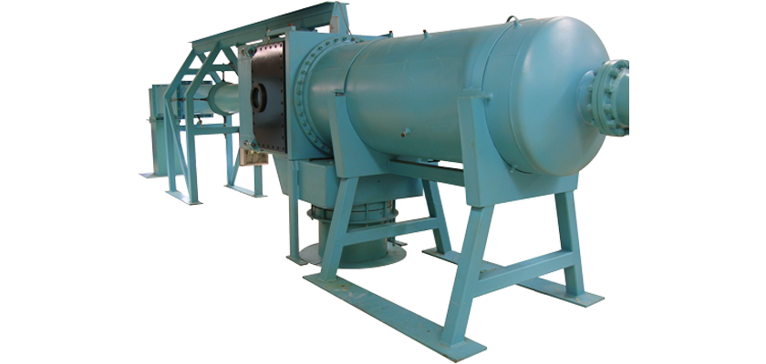
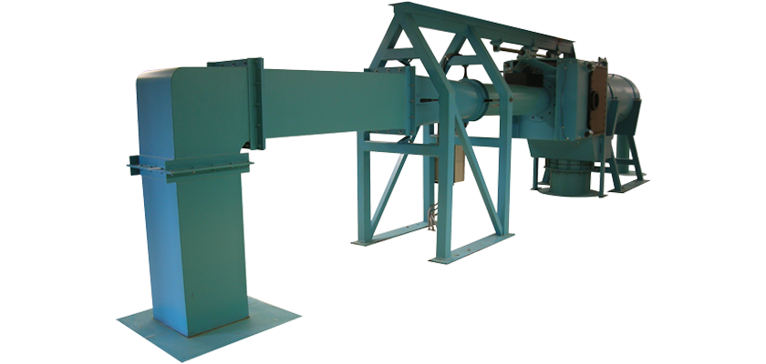
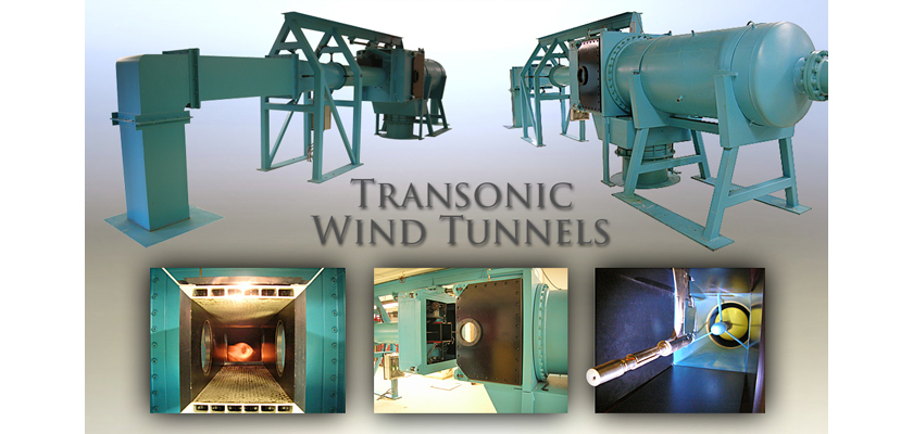
Using compressed air, AEROLAB Transonic Wind Tunnels offer running speeds of M=0.3 to M=1.3.
Employing variable test section porosity, computer-controlled valves, chokes and flaps, target airspeeds are easy to achieve and maintain. Systems with test section sizes of 8-inch x 8-inch (20.32cm x 20.32cm) and 20-inch x 20-inch (51cm x 51cm) are available.
Performance Specifications
- Nominal Mach Number Range: M=0.3 to M=1.3
Detailed Description
- Electro-mechanical Pressure Control Valve – Controlled by the included AEROLAB Data Acquisition, Display and Control system, this device provides fast ramp-up and stable stagnation pressure.
- Stagnation Tank – An ASME Code (certified to 200 psi – 1.28 MPa) bell-shaped tank with a steel perforated flow-smoothing baffle plate acts as a “stagnation” or “settling” chamber.
- Honeycomb Flow Straightener – High quality, high-aspect-ratio aluminum honeycomb flow straightener is installed in all AEROLAB transonic tunnels.
- Turbulence-reducing Screens – Two, 20 x 20 mesh screens smooth the flow before it enters the contraction.
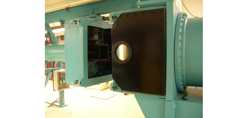
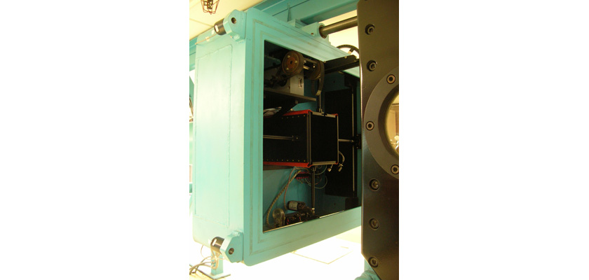
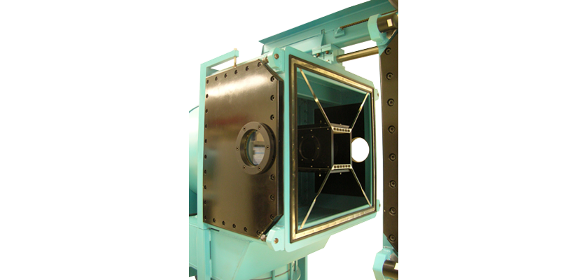
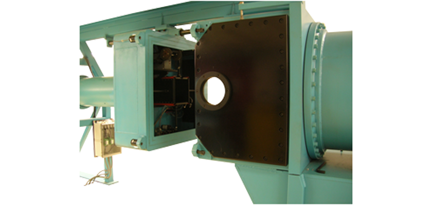
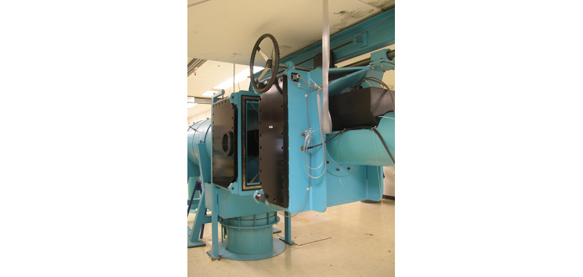
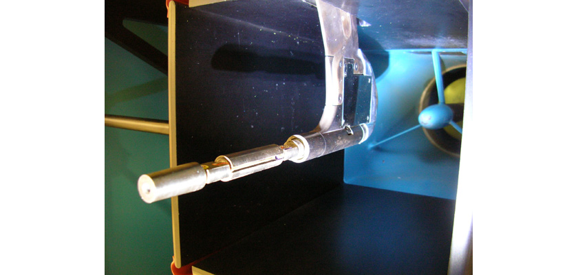
- Test Section – As compared to subsonic or supersonic wind tunnels, transonic test sections are rather complicated. Housed within a “clamshell” pressure vessel, the aluminum test section employs variable-porosity ceiling and floor plates. Additionally, a downstream test section “extension” with adjustable pressure flaps works in unison with other wind tunnel components to produce and maintain the target airspeed.
- Windows – Because the transonic test section is housed within a clamshell pressure vessel, AEROLAB installs polished plate glass windows on all four side walls (two test section side walls and two clamshell side walls). Selected for clarity and uniformity, these windows allow for Schlieren observations and photography.
- Static Pressure Port – Test section static pressure can be used to calculate Mach number. A static pressure port is available in the test section side wall for this purpose.
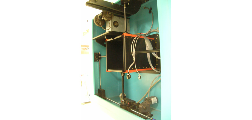
- Model Positioning System – Conveniently mounted to a post above the test section “extension” (adjustable control flaps), a “quadrant” style model positioning system is supplied. Controlled by the Data Acquisition and Control System, pitch angles are accurately measured and repeatable.
- Choke – A vital component of the transonic wind tunnel is the variable choke. Positioned downstream of the test section, the choke works in concert with the stagnation pressure control valve, variable test section porosity and test section extension pressure flaps to achieve and maintain target airspeed.
- Diffuser – Immediately downstream of the choke is a series of diffusers. The diffusers serve to reduce the airflow speed. At this point, the flow can be emptied into the laboratory environment directly or plumbed to an optional acoustic silencer.
- Data Acquisition, Display and Control System – This system displays (real time) and records storage tank pressure, stagnation pressure, stagnation tank total temperature, test section control flap position, choke setting, test section static pressure, “sting” force balance output (optional) and model pitch angle. The system controls stagnation pressure, flap position, model pitch angle and choke setting. Based on a desired Mach number, the program offers an approximate stagnation pressure set point and choke position. A Dell desktop computer and an executable LabVIEW file (LabVIEW software is not needed) are supplied with the system.
Optional Features
- Strain-gauge “sting” balance w/ model pos. quadrant
- Specialty models including AGARD, force missile and pressure missile
- Acoustic Silencer
Related Products
Type
- High Speed
Performance Specifications
- Nominal Mach Number Range: M=0.3 to M=1.3
